|
Home > Electrical
Equipment > Low-voltage equipment
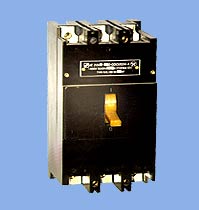
Automatic three-phase
circuit breakers AE20
|
AE 20 and AE 20M
is a family of automatic circuit breakers that are designed for operation in electrical
circuits voltages of up to 660 V AC 50-60 Hz, up to 380 V 400 Hz. AE20 XXX-XXX-XXXZX:
AE
- automatic circuit breaker;
20 - design number;
X
- circuit breaker size, depending on the rated current:
2
- 16 A;
4 - 63 A;
5 - 100 A;
6
- 160 A;
X - number of poles combined with maximum-current release
devices:
3 - triple pole with electromagnetic maximum-current
release devices;
4 - single pole with electromagnetic and
thermal maximum-current release devices;
6 - triple pole
with electromagnetic and thermal maximum-current release devices;
X
- M letter presence - for circuit breakers modernized for the rated currents 63
and 100 A;
X - availability of free contacts:
1
- no free contacts;
2 - one free front contact;
3
- one free back contact;
4 - one free front contact and
one free back contact;
X - auxiliary release devices:
0
- no auxiliary release devices;
2 - independent release
device;
X - thermal compensation and adjustment of the thermal
release device's rated current:
R - adjustment of the thermal
release device's rated current and thermal compensation;
N
- adjustment of the thermal release device's rated current without thermal compensation;
B - no adjustment of the thermal release device's rated current and thermal
compensation for distribution points (with smaller overall dimensions);
O
- no adjustment of the thermal release device's rated current and thermal compensation;
XX - protection rate:
00 - IP00;
20 - IP20;
54 - IP54 (for AE20M family
circuit breakers);
HZ - climatic construction (U, T and placement
category according to GOST 15150-69);
X - wear-resistance class
(A - first class; B - second class).
| Specifications
| AE 2036M |
AE 2046M | AE
2046 | AE 2056MM
| AE 2056MP |
AE 2066 | |
Nominal voltage, V | ~ 660
| ~ 660 |
~ 660 | ~
660 | ~ 660 |
~ 660 | |
Rated current, A | 25 |
63 | 63 |
100 | 100
| 160 |
| Rated current of the thermal overload
release
devices, A | 0.3; 0.4; 0.5;
0.6; 0.8; 1.0; 1.25; 1.6; 2.0; 2.5; 3.15; 4.0; 5.0; 6.3; 8.0; 10.0; 12.5; 16.0;
25.0 | 0.6; 0.8; 1.0; 1.25;
1.6; 2.0; 2.5; 3.15; 4; 5; 6.3; 8; 10; 12.5; 16; 20; 25; 31.5; 40; 50; 63 |
10; 16; 20; 25; 31.5; 40; 50; 63 |
80; 100 | 16;
20; 25; 31.5; 40; 50; 63; 80; 100 | 16;
20; 25; 31.5; 40; 50; 63; 80; 100; 125; 160 |
| Electromagnetic release device cut-off ratio
|
12In |
12In |
12In |
12In |
12In |
12In | | Number
of ON-OFF
cycles |
63,000 |
63,000
(0.6-25 A)
30,000
(31.5-63 A) |
10,000
(up to 40 A)
8000
(up to 63 A) |
1250
(80; 100A) |
40,000
(16-63 A)
25,000
(80; 100 A) |
8000
(16-63 A)
6300
(80; 100 A)
1250
(125; 160 A) | |
Protection level | IR20
| IR20 |
IR20 | IR20
| IR20 |
IR20 | |
Overall dimensions,
mm | 107x56x85
| 145x75x105 |
207x75x120 | 207x75x120
| 207x75x120 |
211x112x122 | |
Weight, kg | 0.42 |
1.06 | less
than 1.6 | 1.2 |
1.6 | 2.3
| | Maximum switching
capacity, kA |
1.5
|
2.5 |
4 |
3.5 |
4 |
6 | | |
Search |  |
Services offered
to our clients | |
Services offered
to our clients | |
|